Official Luthiers Forum! http://mowrystrings.luthiersforum.com/forum/ |
|
Fretboard Radius Jig (lots of pics) http://mowrystrings.luthiersforum.com/forum/viewtopic.php?f=10102&t=13639 |
Page 1 of 1 |
Author: | Kim [ Fri Sep 14, 2007 8:39 pm ] |
Post subject: | |
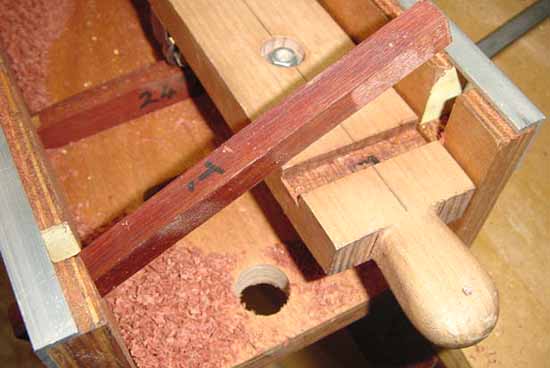
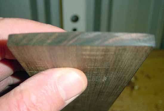
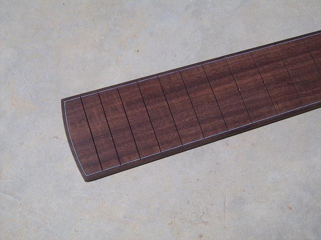
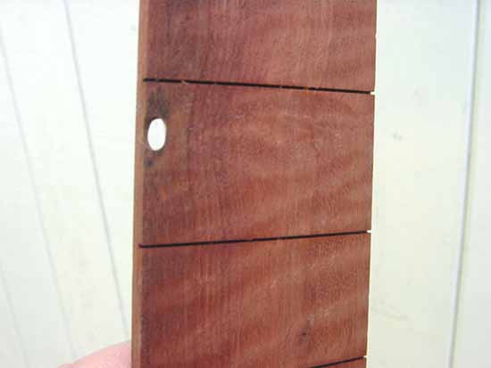
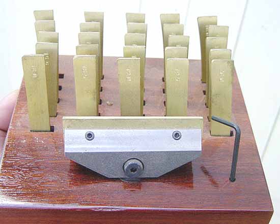
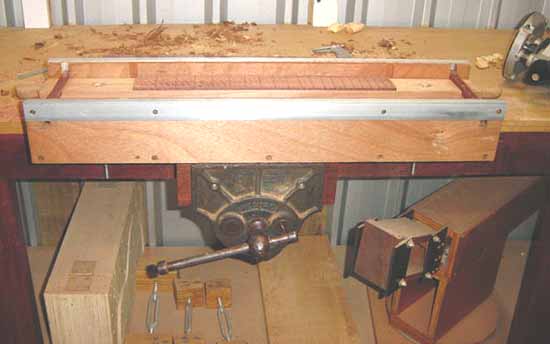
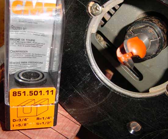
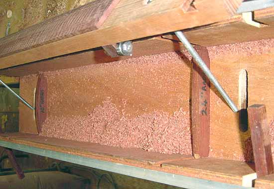
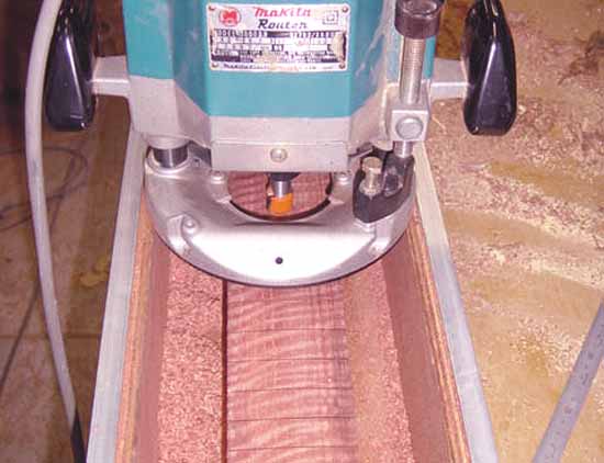
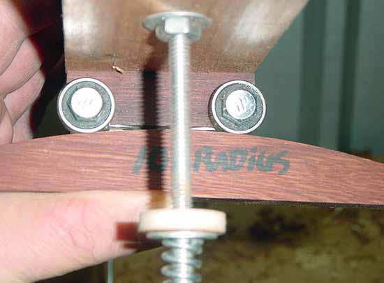
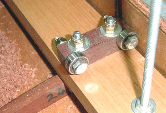
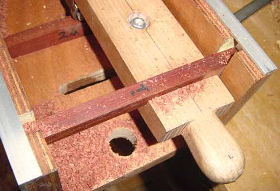
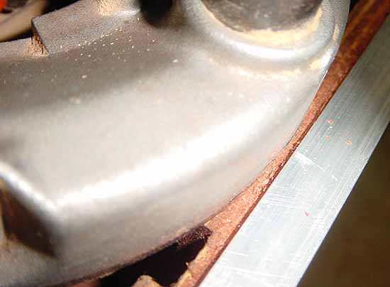
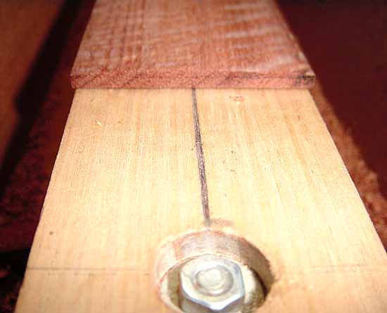
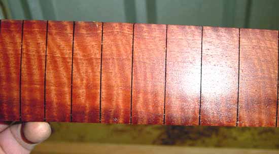
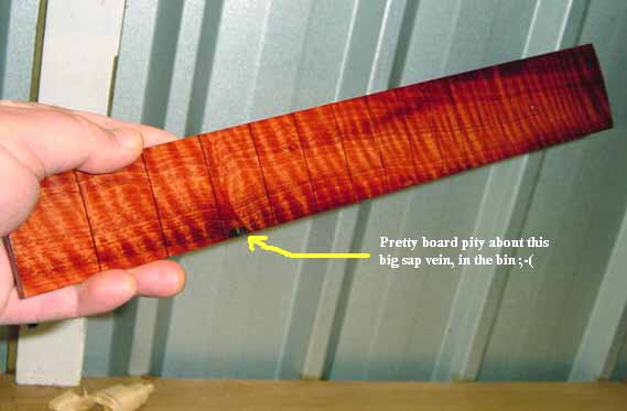
Hey all, A while back, JJ posted a topic about a fretboard radiusing jig he made using plans he bought from Rick Micheletti of Luthier Cool Tools. HERE is a link to that thread and what I have written here in this thread will make more sense if you check JJ's out first. After reading JJ's thread, I bought some plans from Rick's ebay store (and a wonderful sinker redwood top as well) and made one of these jigs. I can now report that it works pretty well and I am happy with the results of my time and effort. There was some discussion in JJ's thread about which router bit to use. Rick had revised the plans by the time I got my copy and this is what is now recommended. It's a 3/4" tray cutting bit. It seemed to me that some in JJ's thread were a little unclear on how this jig actually worked so I took some images to try and clarify a few things and a closer image of the carriage block bearing assembly and radius guide just held together by hand so those interested can have a closer look. If you read JJ's thread, he explains the process very well and these images are just to focus on the details of the system and to act a a supplementary to his post. Basically the slotted fretboard is secured to a carriage board using double sided tape. The carriage board is held static under spring tension onto a pair of exchangeable radius profiles which are slotted into rebates let into the sides of the jigs main structure. The router is held in track by the 2 aluminium guides which can be seen in the image displayed below. The router is progressed along the jig between these 2 aluminium guides and passes over the fretboard completing a pass. Once a pass has been performed, the user then makes a small incremental advance of the carriage board over the pair of radius profiles at the very base of the jig. The carriage board, which is fastened to bearing blocks located at either end, rides across the selected radius profiles upon bearings which in theory results in the desired radius being reproduced into the surface of the fretboard. The above image also shows the carriage tension system and the UH plastic washer which allows smooth advancements of the carriage board to be made when required. This is the guts of the system as it holds the carriage board secure and allows you to keep both hands on the router during each successive pass. A closer look at the bearing block. And the spring loading mechanism when in place on the jig. The carriage board is also prevented from moving around during a pass by two hardwood guides or stabilizers which are let into corresponding rebates cut into each end of the carriage board and those into main structure of the jig itself. To ensure smoothness in operation of the router along it's path, a gap of app 1/16" left between the router base and the guide rails of the jig. This should be the only play in the jigs operation and for best results should be considered in operation with the user making a first pass bearing lightly upon one side of the jig, and a returning pass bearing upon the other. As can be seen here in the images below the end results are very good for a single cut radius. These are end shots of 2 different fret boards the lower one is a 16" profile and checks perfect with those little stewmac gauges. As I mentioned above, in theory this jig will cut the same radius as the profile which is inserted into the rebate. If this were so in practice, this jig would be ideal for making a compound radius fretboard. However unless I done something wrong in putting my jig together, this has not proven to be the case in practice. I tried to make a compound radius board today by placing a 24" profile at the 22nd fret end and a 10" radius profile at the nut end. I found the result was heavily biased toward the 10" radius over the full length of the board. Maybe this selection was too extreme but I found that the 24" end was not only of a more acute radius than it should have been, but also that it was much less uniform in the arch of radius. I do however think that this jig would work OK for a compound of say 16" to 22" and for a singular profile it is very accurate and produces a radius fretboard with a profile of your choice from any of the many templates provided with the plans, which then requires VERY little sanding straight from the jig. As I said above, all things considered, I am happy with the result of my time and effort and happy with the jig............ Even if this one did end up in the bin But that was not the jigs fault, it was heading there anyway due to a big fat gum vein. Can any of our members outside of the Australia tell us what kind of wood this is pictured above?? Or what kind of wood this is pictured below?? Cheers all Kim |
Author: | Dennis Leahy [ Fri Sep 14, 2007 10:49 pm ] |
Post subject: | |
Hi Kim, Nice views of the working parts of your jig! Is that first fingerboard curly Jarrah? That sap pocket looks like an opportunity for an inlay! I know that gorgeous wood "shouldn't" need any inlay to dress it up, but maybe you'll be able to think of something - possibly even dressing it down. For instance, one of the members here (can't think of who) did a series of seasonally themed guitars, and had wooden Fall leaves inlaid into the fingerboard (and wrapping over onto the soundboard.) When you say "bin" I hope you don't mean trash bin, but maybe at worst scrap bin, waiting for a use. Dennis |
Author: | KenH [ Sat Sep 15, 2007 2:08 am ] |
Post subject: | |
Perfect timing Kim! I have been wanting to build myself one of these and now I have a good idea how to do it. THANKS !!! |
Author: | grumpy [ Sat Sep 15, 2007 2:53 am ] |
Post subject: | |
No need to lose that fretboard! if the pocket is too soft, dig out the sap, and fill it wit an epoxy sawdust mixture. The trick here is to leave a natural, rough edge around it when digging it out. if the surrounding area is too nice, it will look like a fix, if you leave it looking naural, it looks, well, natural. |
Author: | Wade Sylvester [ Sat Sep 15, 2007 3:04 am ] |
Post subject: | |
Kim, Great looking jig! Thanks for all the detailed pics. One question. Since the fretboard sits almost 2 inches higher than your 10’ radi template, wouldn’t that mean you are cutting a 12 inch radi into the board? Maybe I'm missing something.. Nice figured boards too! |
Author: | PaulB [ Sat Sep 15, 2007 12:11 pm ] |
Post subject: | |
Mario, Kim's just teasing us by throwing out that fretboard. That stuff grows on trees in his neck of the woods. I could hazard a guess as to what it is but I won't. That second fretboard looks kinda familiar. Tho, my pic doesn't show as much figure, it's actually about the same as Kim's. The bucket of lard will have to go to one of you foreign types. |
Author: | Kim [ Sat Sep 15, 2007 5:15 pm ] |
Post subject: | |
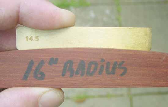
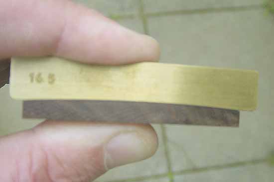
Thanks all, OK, so Dennis grabs the lard for naming the first board, it is indeed Jarrah. As is the bench, all the hardwood components of the jig, and everything else around here that needs to be made strong, stable, and durable, even my old house is all Jarrah framed, the whole thing, studs, noggins, joist, purlins, window and door frames, everything. Even the floors are Jarrah and she's clad with Jarrah weatherboards. I must admit she does look a bit of a basket case now days but she's still solid and strong in any storm even though she was put together on this site in 1951 from bits and pieces of buildings that where bought down from the Murchison gold fields first constructed up there at Reedy's Gold Mine in the 1850's, yep, Jarrah is good wood I think Paul has shown that he is onto the second board but mine is the western variety from out around Coolgardie and is apparently a little different from the rest found in AU, both very nice though. Mario, the sap hole in the Jarrah board is quite large, one could fill it or make a feature I suppose, but it will always be noticeable. The board is also a shorty only being long enough for 20 fret, so it was always a target for experimentacion, I needed wood, it got too close . Wade, your not missing anything mate, in fact your spot on with your observation. It appears that Rick has made allowances for the increased radius that the carriage board is forced to follow over the radius profile by decreasing the actual radius of each marked template that is provided with the plan. To demonstrate this I have used a couple of the very accurate fret caul insets from the set that I got from John Watkins of CNC Guitar Parts, he's a member here at the OLF so PM him if you need some of these high quality tools....Oh yeah, the holder is also Jarrah Anyhow, as you can see here the radius profile marked as 16" is in fact 14.5", this was probably meat to be 14" but I probably got a touch over enthusiastic when shaping So the result of using this profile in the jig is actually a 16.5" radii but that's OK, at just a couple of thou difference, Ill take it. A note about building this or any other jig, firstly if you can get a good plan don't skimp, it is worth the effort and expense to do so. Trying to reinvent the wheel is pointless and can fast lead to a large pile of frustratingly unsatisfactory results. Look at Rick's Site the plans are reasonably priced and you will not only be assisting yourself, you will be giving credit where due. Also, for the noobs, when ever your making a jig, take your time. Be meticulous with your measurements and workmanship as the end result will live with you for a long time. Build in an error, and you have defeated the purpose of the jig, you have waisted time instead of saving it. Any inaccuracies ignored or unnoticed are destine to be repeated in your end product every time you use the tool and an example of this is demonstrated above with my fretboard having a radius of 16.5" rather than the 16" intended, sure an easy fix, but it still smarts that I missed it the first time. Cheers Kim |
Author: | erikbojerik [ Sat Sep 15, 2007 11:31 pm ] |
Post subject: | |
[QUOTE=larkim] As I mentioned above, in theory this jig will cut the same radius as the profile which is inserted into the rebate. If this were so in practice, this jig would be ideal for making a compound radius fretboard. However unless I done something wrong in putting my jig together, this has not proven to be the case in practice. I tried to make a compound radius board today by placing a 24" profile at the 22nd fret end and a 10" radius profile at the nut end. I found the result was heavily biased toward the 10" radius over the full length of the board. Maybe this selection was too extreme but I found that the 24" end was not only of a more acute radius than it should have been, but also that it was much less uniform in the arch of radius. [/QUOTE] Thanks for the detailed post, I'd heard about this jig and always wondered how it really worked. I'll venture that you've put it together just fine....there is a simple reason this jig won't work well for a compound radius. This is because, even though you have the two different radius profiles installed in the jig, in order to cut the compound properly the board has to swing horizontally underneath the router if the bearings are to follow a proper path on the radius templates. The easiest way I can explain it is to think of the 3D shape that you're routing underneath the router. For a constant radius, your fretboard surface is a surface section of a cylinder, whose rotational axis is parallel to the path of the router bit. For a compound radius, your fretboard is a surface section of a cone...and because the rotational axis of a cone is not parallel to the path of the router, it won't quite work out. |
Author: | Kim [ Sun Sep 16, 2007 8:59 am ] |
Post subject: | |
Yes, doubt about the ability of this jig to cut compound radii was raised in JJ's thread and the concept just never has sat well with my minds eye. To successfully cut a compound, I would think that the carriage board would need to twist slightly upon it's axis to allow each set of bearings to ride true upon their respective profile. I can tell you that piece of 1/4 sawn tassi oak I have used is not twisting for anybody, if it could it would not even be any good for a singular radius as it would flex away from the router bit in the centre. Hoping JJ will jump in here with his experience but as I said above, it is a good jig for cutting a large variety of singular radii and can be changed from one to another very quickly and it results in a fretboard which requires very little sanding straight from the jig. Cheers Kim |
Author: | KenH [ Sun Sep 16, 2007 10:52 am ] |
Post subject: | |
Does anybody actually just sell the jigs already made? I would love to have one of these, but I just dont have the time to stop building guitars to build one. |
Author: | SniderMike [ Sun Sep 16, 2007 11:59 am ] |
Post subject: | |
I don't see why it couldn't cut a compound radius. The outside of the "cone" just has to be parallel to the path of the cutter, instead of the axis, at least in my mind. If you actually have a cone of some sort, why wouldn't a sled with 2 wheels on each end not be able to roll on it and follow its curves? I don't think it would move down the cone during its rotation, but it shouldn't matter for such a short trip. Am I missing something? |
Author: | Kim [ Sun Sep 16, 2007 7:21 pm ] |
Post subject: | |
Well Mike, ill try and explain what I am seeing. With this jig, you have 2 bearings at each end and each bearing is acting as wheel and the solid block to which those wheels are bolted is acting as a chassis. When attempting to perform a compound radius cut, each pair of these wheels is expected to remain firmly in contact with it's chosen radius guide insert. Now this would be fine but for the fact that we have joined these two otherwise independent pairs of wheels together by bolting them to the carriage board. This link is what creates our problem. For when we have a degree of difference between the radius guides, say 1 @10" and the other @24", (and I expect things to be much the same even with more closely matched radii) contact of both sets of wheels with their respective radius insert becomes impossible due to the rigidity of the carriage board. This rigidity demands that only one of two pairs wheels can maintain FULL contact with it's radius insert, the other end, the end with the least spring tension is forced to lift one wheel from the surface of it's guide to conform to the radius of the more dominant end. If the end with the gentlest arch, in this case the 24" radius, had more dominant spring tension, then the set of bearings or wheels riding upon the 10" radius would necessarily need to lift that bearing or wheel which is furthest from the apex of it's radius in order to conform to the gentler shape of the more dominant arch. If you applied more tension to the 10" end, then the wheel closest to the apex of the lesser arch would be lifted. To my mind, the only way you could achieve having both sets of wheels or bearings in contact with their respective radius inserts all at the same time is if a twist occurred in the carriage board itself. This of course leads us to the question of, what would happen if you constructed the carriage board from a series of independent slats, the lateral movement of which would allow the carriage to conform to the separate radii? Well, of course then the double sided tape would come loose and you BRW fretboard would become a chewed up shattered mess. Cheers Kim |
Author: | Kim [ Mon Sep 17, 2007 12:38 am ] |
Post subject: | |
bump'in looking for JJ's comment. |
Author: | erikbojerik [ Mon Sep 17, 2007 1:24 am ] |
Post subject: | |
Nope...twist is not what you want. Try this. In order to cut the compound correctly, the bearings have to ride along an arc on the circumfrence of a circle with a given radius...and this arc also defines an angle on the circle (like a piece of pie on a pie chart). If the radii of the circles at each end of the jig are different, you'd need to have the jig sweep the board through the same angle on both circles...but because the length of the arc on the larger circle is longer than on the smaller circle, the flatter-end of the board will have to swing in and out as well as sweep through the angle...this is how Grizzly's sanding jig works. |
Author: | SniderMike [ Mon Sep 17, 2007 1:40 am ] |
Post subject: | |
[QUOTE=erikbojerik] If the radii of the circles at each end of the jig are different, you'd need to have the jig sweep the board through the same angle on both circles...but because the length of the arc on the larger circle is longer than on the smaller circle, the flatter-end of the board will have to swing in and out as well as sweep through the angle...this is how Grizzly's sanding jig works. [/QUOTE] I think this is along my lines of thought. If you try to move both ends of the carriage board the same amount one way or the other, I would expect a wheel at one end to lose contact. But if you move the end of the carriage board on the larger radius a bit more, I think you maintain contact. If I'm imagining it correctly, that shouldn't be a big deal. Maybe with those guide bars on top of the carriage you can't do that though??? |
Author: | JJ Donohue [ Mon Sep 17, 2007 2:30 am ] |
Post subject: | |
Hey Kim...great tutorial. Sorry I'm late in jumping on but I was traveling since last Thursday. It looks like you did an excellent job of following Rick's plans. I love the jig and have found it to be simple and accurate to use for single radiused boards. Since building the jig, I have only radiused 3 FB's and it has since been collecting dust until my next effort. I have not done any multi-radiused boards yet but will look into some trials in the near future since I will need that feature on an electric neck I'm building. I suspect that Mike's thoughts on achieving the compound radius are correct but we should try to confirm. I agree with you that the plans are excellent but for the mistake in listing the router bit needed on my version...hopefully that has been corrected. |
Author: | JJ Donohue [ Mon Sep 17, 2007 2:37 am ] |
Post subject: | |
...EDIT... There is one significant difference in our jigs, Kim. Rick's plan doesn't show this but I found that mounting the router on a slippery square mounting plate made the operation a lot more stable and accurate. (check the pic in my original thread) In my first trials, I found that a rounded base could tip if one was a bit clumsy (like me!) so I made the dedicated base...it rides flat, true and friction-free. |
Page 1 of 1 | All times are UTC - 5 hours |
Powered by phpBB® Forum Software © phpBB Group http://www.phpbb.com/ |